How to build your own PC Driven remote control car?
This page has been created as part of my contribution to National Science Week 2006 at the University of Wales, Aberystwyth. It is intended for kids age 11-14.
A PC Driven remote control car can be built fairly easily and mostly using parts you can (probably) find lying around (or at least that could be found in 2006). We recommend you get an adult to help you with the soldering of wires as this can be a dangerous thing to do especially if you've not done any soldering before.
How does it all work?
There are 3 key things to this remote control car. The parallel port on the computer, binary code and transistors.
Binary Code
Binary code is a code used by computers to represent numbers. It works using only two digits 0 and 1.
Normally we count using 10 digits (0,1,....9) and write numbers in columns of 1s, 10s, 100s etc. In binary code we only use the digits one and zero but we place them in columns of 1s,2s,4s,8s etc. So the number two is written 10, three is 11, four is 100, five is 101, six is 110 and so on. Each digit in binary is known as a bit.
For more information on binary have a look at this page.
The parallel port
The parallel port (also known as the printer port) is able to send 8 bits at a time to a device (originally intended for printers). This is done using 8 separate wires, one for each bit. We can control which wire's get turned on through the numbers we send to the parallel port. For example if we send the number "1" only the first bit gets turned on as 1 in binary is 0000001. If we send the number "255" then all bits are turned on as 255 is 11111111 in binary.
More information on the parallel port can be found on the following pages:
Transistors
A transistor is a special kind of switch which is turned on and off by electricity rather than by pressing it. To make the remote control cars we replaced the switches in the controller with transistors and used the PC's parallel port to make them turn on and off.
For more information on transistors have a look at this page.
Things you will need
You may find you have most of the parts already, if not you should be able to get all the require parts for under £50.
A PC with a parallel port.
The parallel port is not found on some newer PCs, but is on most older ones. A parallel port has two rows of holes in it, the bottom row has 12 holes and the top row has 13. There is a very good web Page showing the pinouts of the parallel port on the Imperial College Website.
If you don't have a suitable PC you can probably get one cheaply from CRAFT in Aberystwyth. A 286,386,486 or Pentium system should work fine. The PC will need a working floppy or CD-ROM drive to load the software on. It will need to be able to run the DOS Operating System and the QBasic programming language.
A parallel port cable
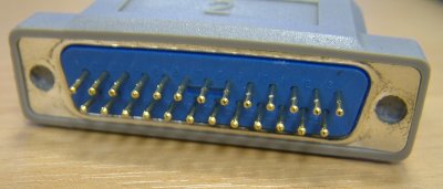
You can get one of these either from a parallel printer cable or from a 25 pin serial port connector which is also used in some older PCs.
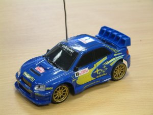
A remote control car
Any remote control car should do, we used the "Subaru Impreza WRC" from Argos (catalouge number 369/4004) which only cost £5.99.
A soldering iron and some solder
This is to join wires onto the remote control unit. This must be done by an adult who knows how to use a soldering iron. A soldering iron can be bought for under £20. Your school technology department may already have one of these.
Four transistors
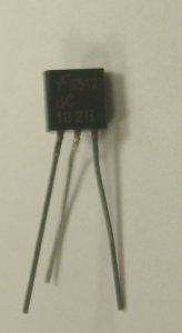
These should be NPN
transistors, they
can be found in many everyday electronics so you might be able to find
them in a broken stereo system. We used BC128A transistors which can be
bought for 8
pence each (minimum order is 5) from Radio Supplies.
Four 1k ohm resistors
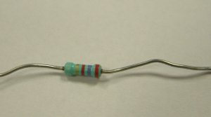
These
are used to protect the transistor from the parallel port. The circuit
may function without them but its safer to use them. You can also buy
these from Radio
Supplies for 2 pence each (minimum order is 10).
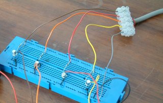
A breadboard or circuit board to place all the electronic components on.
A breadboard is a board with holes in that you can put electrical components in, this is what we used. It doesn't need any solder to join components together. You could also use veroboard which is similar but means you'll have to solder everything in place or you can make a printed circuit board. If your interested in doing this have a look at these webpages:
How To Make a PCB: Ozan and Kristof explain.
Building an LED caselight (shows how to use Veroboard).
The program code
Basic Version:
A floppy disk or CD-ROM with Dos and QBasic on it.
Dos is an old operating system which many PCs used to use. It is also be basis of Windows 95,98 or ME. You will need a programming language called QBasic to use the programs supplied here, this programming language was supplied free with the Microsoft versions of Dos and with Windows 95,98 and ME. It can most likely be downloaded from the internet (try searching for qbasic in your favourite search engine) as well, but only do this if you already own a legal copy of MS-DOS or Windows 95,98 or ME.
A copy of our QBasic program code.
We wrote several different programs.
The main program which we demoed for National Science Week is available here. This program works by letting you control the car with the arrow keys and each press of the key moves the car a little. This program has some quite complicated bits which work out how long to turn the motors on and off for.
A very simple program just turns on right motor and leaves it on according to key which has been pressed. This makes the car go very fast and you'll need a big open area to make it work. To stop the car press the / key.
A simple diagnostics program lets you enter numbers and to choose which motor(s) get turned on.
The Linux Version
For 2007 National Science and Engineering week I rewrote the code for Linux using SDL. This code will require gcc,gcc-c++ (g++), libSDL, libSDL-Image and their development headers to be installed. I developed and tested the code on Mandriva 2006 and 2007 but it should work on most Linux distributions. SDL code is highly portable, only the file parport.c (which is about 25 lines) should be Linux specific so please feel free to convert it to other operating systems.
This version gives a much more responsive feel to it and you can play by holding arrow keys down (in QBasic you had to tap them). To make things harder this version also increases the delay between pressing a key and something happening (delay starts at 10 milliseconds and goes up to 2 seconds) and limits playing time to two minutes.
The Linux version is available here.
How to build it?
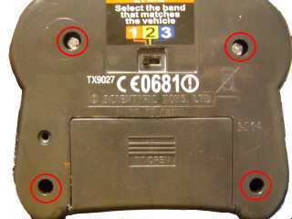
This page assumes you've used a Subaru Impreza Remote Control car from Argos.
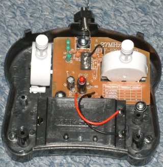
1. Unscrew the remote control unit
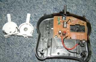
2. Remove the two control levers
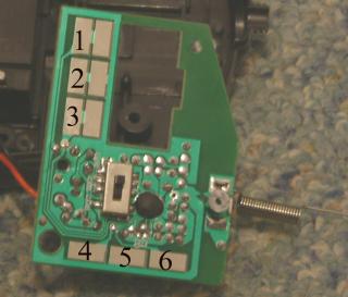
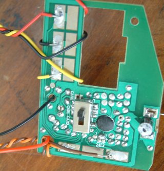
3. Solder wires onto pads for the control unit. The middle pads form
the ground and the pads at each end are the signal wires. The diagram below numbers each of the pads. If you join a wire between
pads 5 and 6 the car will go forward, pads 4 and 5 make it go
backwards, 1 and 2 make it go left and 2 and 3 make it go right. Pads 2
and 5 are both the ground of the battery and actually are connected to
the same thing so in making our circuit we only need to solder on one
of them. It helped to wrap wires around the board so that if anything pulled on them it wouldn't rip the connection off.
4. Strip
off the wires for your parallel port connector, you will
need one ground wire and the 4 data wires. These are connected to pin
numbers . Pin numbers are usually written on the front of the parallel
port connector. It can be helpful to use our diagnostics program when
working out which wire is which. You can test the parallel port by
placing an LED (A light bulb won't work) between the data pins and the
ground pin.
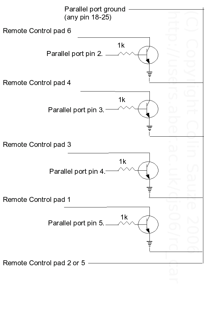
5.Connect each of the 4 data wires to the base of each transistor.
6. Connect the wires from each of the pads to the collector of the transistor.
7. Connect the ground from one of the pads to the emitter of the transistor.
8. Connect the ground of the parallel port to the ground of the batteries. We found it helpful to desolder the LED which was connected to the
circuit board. This LED wasn't needed and removing it made it easier to
solder other things on.
A complete circuit diagram is shown below (or its available as an Eagle circuit diagram - here):
Using other programming languages and controlling other devices.
Using other programming languages
You can program the parallel port in just about any major programming language including Visual Basic, C, C++, Pascal, Java or Delphi. Here are a few links to programming the parallel port in other languages:
- Programming the Parallel port in Windows (Under Visual Basic or Visual C++)
- Programming the Parallel port under Dos in Turbo C++/Borland C++
- Programming the Parallel port under Linux in GNU C (GCC)
Controlling other devices
You can use the techniques shown here to control nearly any electrical device. In the interest of safety, DO NOT try and control mains devices with this technique as mains electricity can kill if something goes wrong.
Instead of connecting up the circuit from a remote control car you can connect up other types of circuit which have switches in them. This could be a bigger remote control car, the on/off button on a mobile phone, a remote control for a TV or a (batter powered) CD Player.